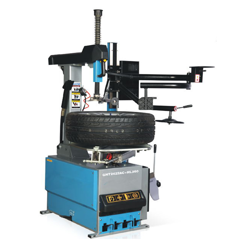
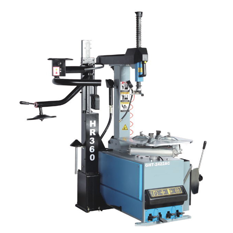
Automatic Racing Tyre Changer And Helper
Feature
1. Foot valve fine structure can be removed as a whole, operation stably and reliably and easy maintenance;
2. Mounting head and grip jaw are made of alloy steel,
3. Hexagonal oriented tube extended to 270mm, effectively prevent the deformation of the hexagonal shaft;
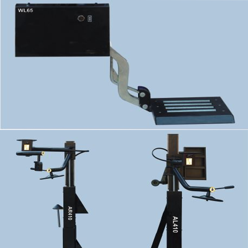
4. Equipped with tyre lifter, easy for loading the tyre;
5. Equipped with the built-in air tank jet-blast device, controlled by a unique foot valve and hand-held pneumatic device;
6. With double helper arm for handing wide, low-profile and stiff tyres.
7. Adjustable Grip Jaw(option),±2”can be adjusted on the basic clamping size.
Specification
| Motor power | 1.1kw/0.75kw/0.55kw |
| Power supply | 110V/220V/240V/380V/415V |
| Max. wheel diameter | 47"/1200mm |
| Max. wheel width | 16"/410mm |
| Outside clamping | 13"-24" |
| Inside clamping | 15"-28" |
| Air supply | 8-10bar |
| Rotation speed | 6rpm |
| Bead breaker force | 2500Kg |
| Noise level | <70dB |
| Weight | 562Kg |
| Package size | 1400*1120*1800mm |
| 8 units can be loaded into one 20”container | |
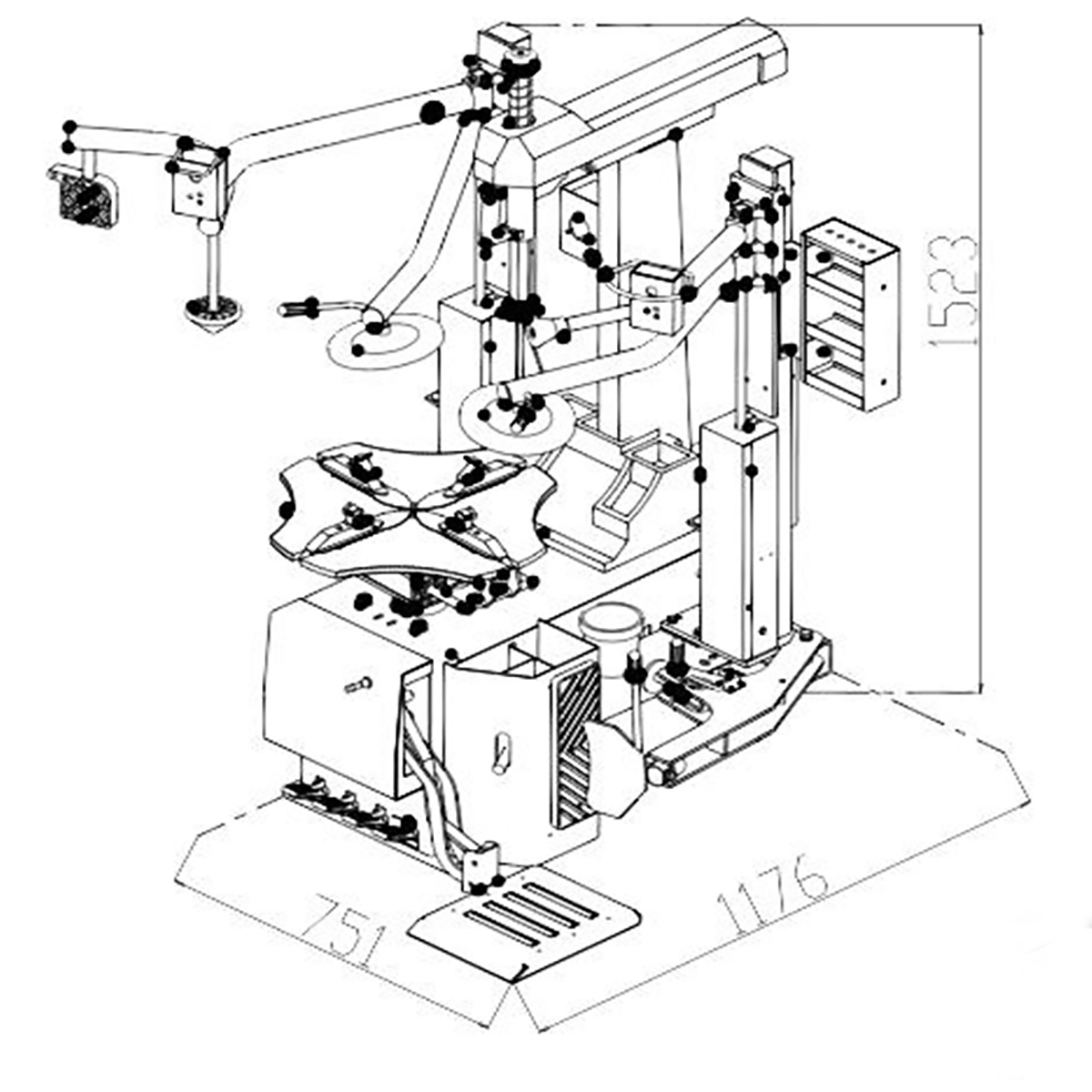
Drawing
Operation Precautions
1. The power supply of the tire machine must be in a normal state. In the non-working state, the power is in the off position. The air pressure of the internal machine is at normal pressure, and the air pipe is not connected in the non-working state.
2. Before replacing the tire, check whether the tire frame is deformed, and whether the air nozzle is leaking or cracked.
3. Unscrew the air nozzle to release the tire pressure, place the tire in the middle of the compression arm, and operate the compression arm to separate the two sides of the tire from the wheel frame.
4. Operate the switches to remove the tires.
5. When the new tires are installed, the tires will be marked upwards, and the tires will be installed by operating the switches.
6. After assembly, each switch should be placed in the off position.